
Core Link Camera
Control Setup Guide
Setup instructions, camera network configuration, pairing, control-device setup, and troubleshooting for Core Link systems.
Low Latency
Fast camera-control response with minimal delay.
Long Range
902–928 MHz operation provides excellent range and obstacle penetration.
Multi-User
Supports one receiver and up to four transmitters.
Pairing & Configuration
Core Link supports multiple system configurations and is designed for quick setup in the field. Complete 1:1, 1:2, 1:3, and 1:4 kits ship pre-configured and paired. Additional units can be paired to an existing system as needed.
1:1 Configuration
For maximum range and performance, configure one unit as an RX and the other as a TX. RX and TX mode is set using the internal DIP switch on the main board.
Dedicated RX and TX units arrive pre-configured and labeled, so opening the enclosure is unnecessary.
Pairing Procedure
- Power on both devices and install the antennas.
- Press and hold the pairing button on both units simultaneously until the LEDs flash.
- Release both pairing buttons.
- Wait for the pairing process to complete.
- Solid blue LEDs indicate a successful connection. The RX unit also displays a red LED indicating Receiver mode.
1:Many Configuration
A single RX can communicate with up to four TX units. Because all communication passes through the RX, its placement is important for maintaining optimal range and reliability.
Add Additional TX Units
- Pair the first TX to the RX.
- Power on the next TX and repeat the pairing procedure.
- Continue until all required TX units have been added.
Bandwidth is shared as additional TX units are connected, which may reduce maximum range. Powering off inactive TX units allows the system to operate like a smaller configuration.
Unpairing
Core Link does not have a dedicated unpair function. To remove a unit from a system, pair it to a different receiver or change its operating mode between RX and TX.
Camera Configuration
Select your camera below and configure the required network and remote-control settings. All cameras use the same quick-reference layout for faster setup in the field.
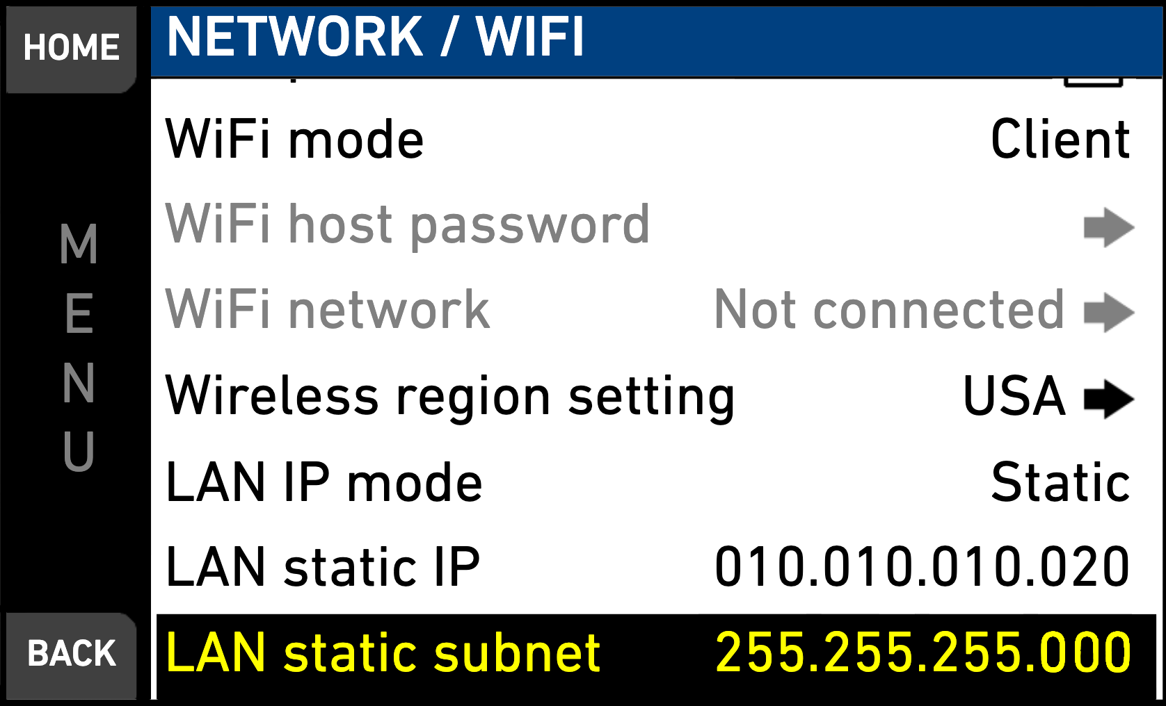
When using Core Link with two or more cameras, make sure each camera is configured with a different IP address. For example, A Cam can use 10.10.10.20 and B Cam can use 10.10.10.21. Never assign the same IP address to multiple cameras.
ARRI Alexa 35
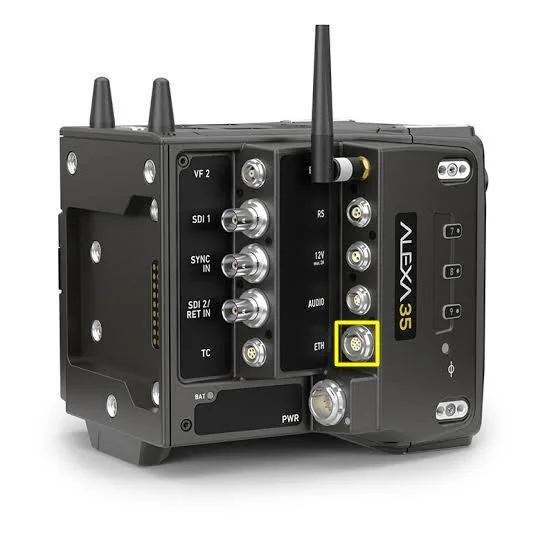
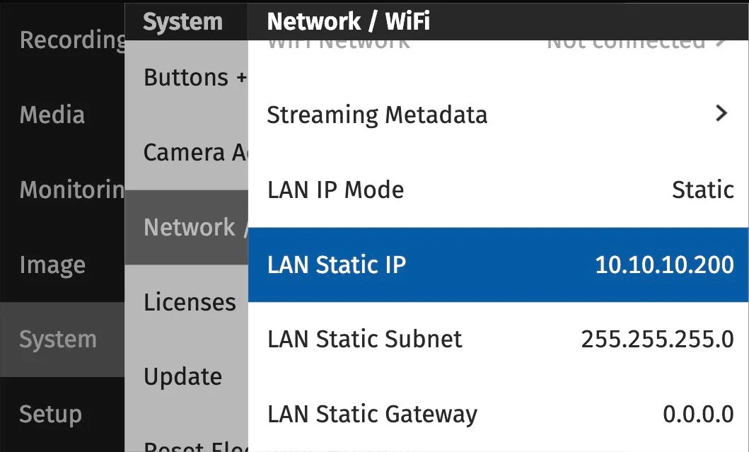
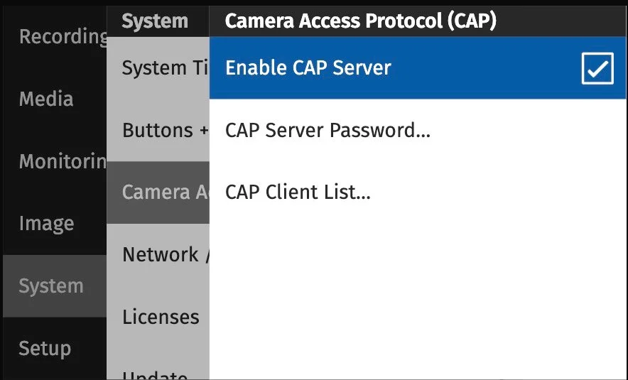
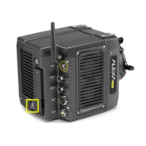
ARRI Alexa Mini LF
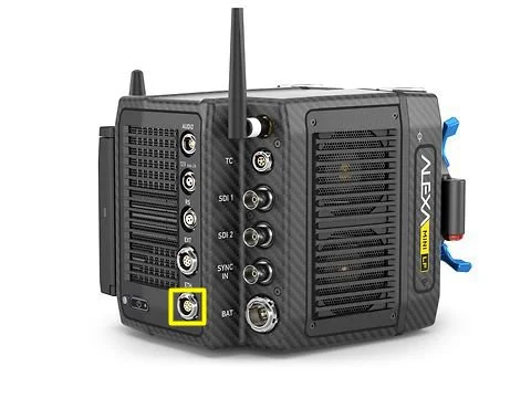
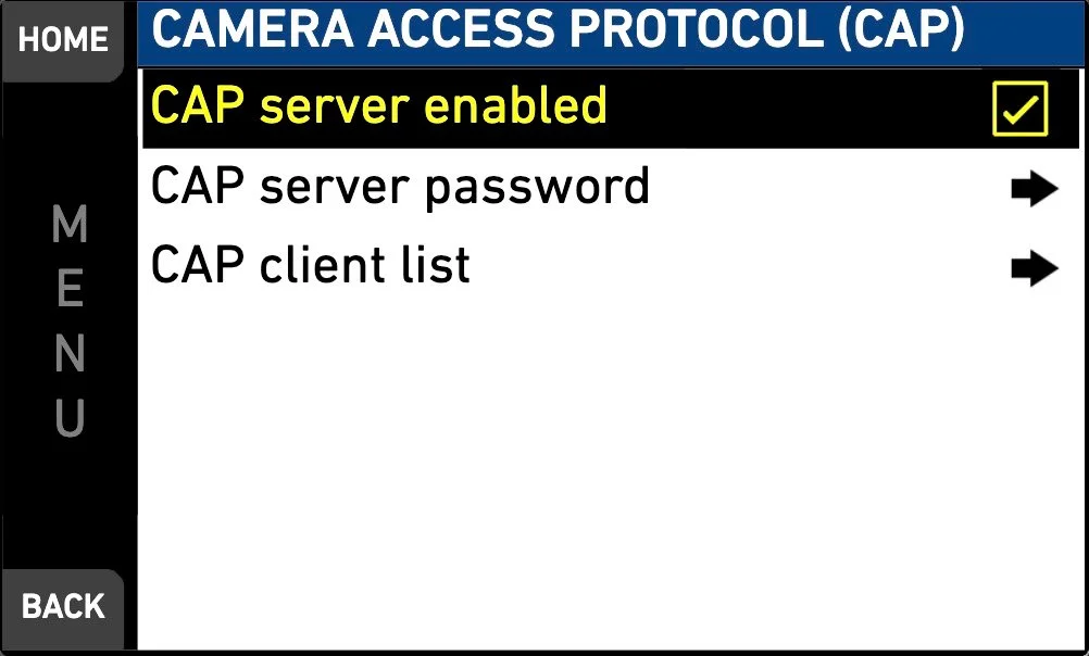
ARRI Alexa Mini
Sony Venice / Venice 2
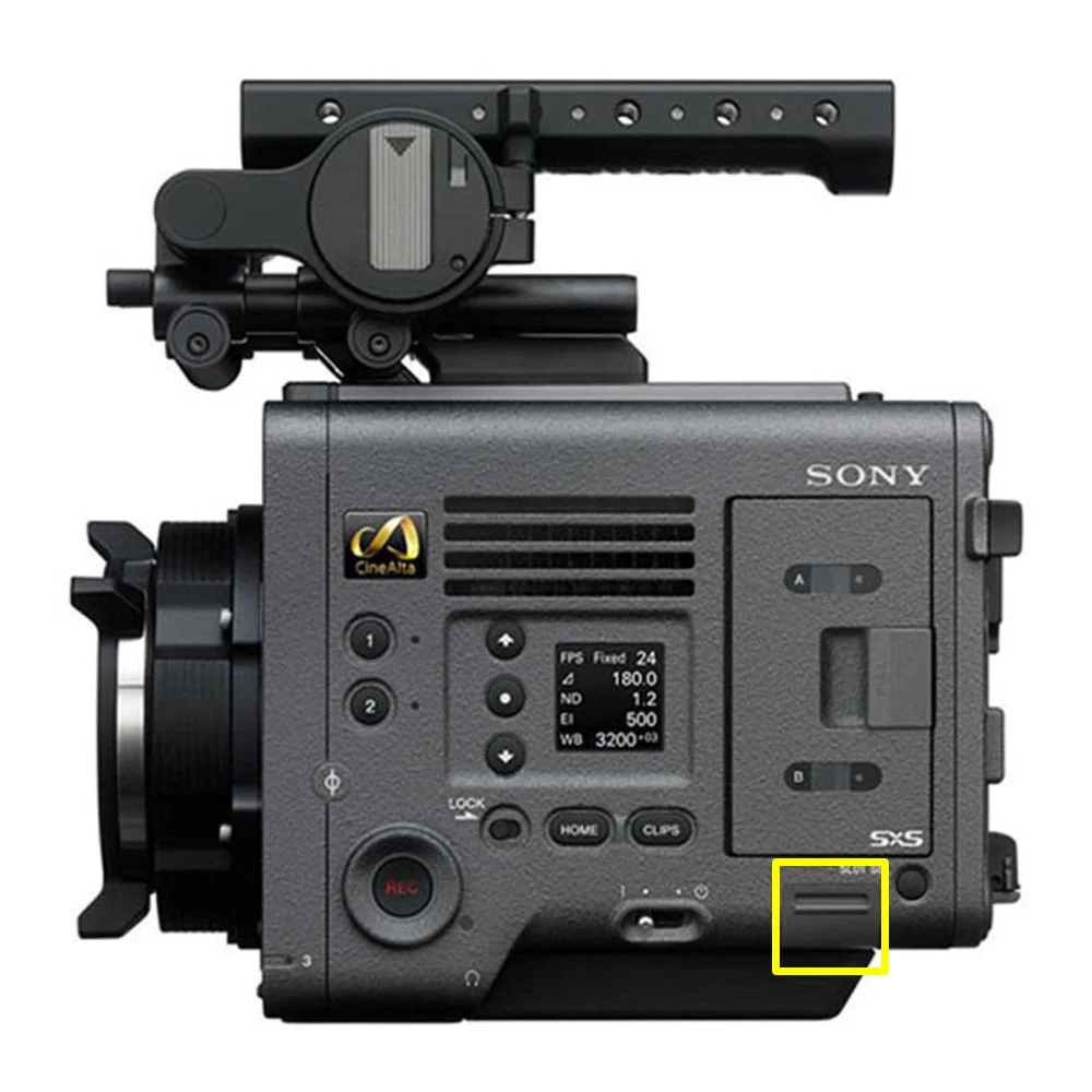
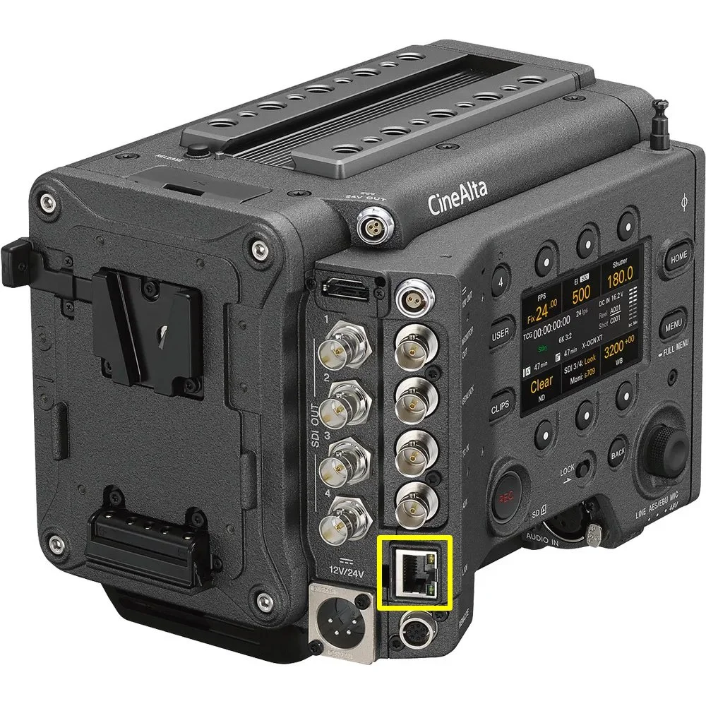
If the camera has an unknown network configuration, perform a Network Reset and power-cycle the camera before configuring Core Link.
Sony BURANO

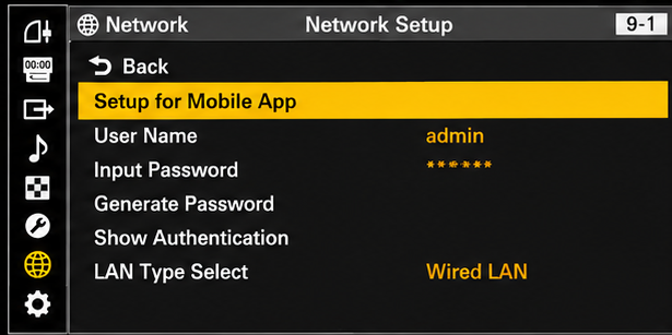
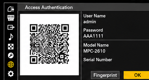
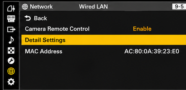
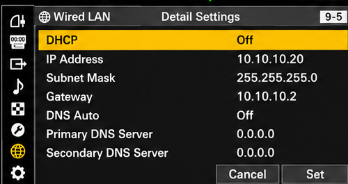
If the camera has an unknown or existing network configuration, navigate to Network → Network Reset, execute the reset, then power-cycle the camera.
Sony FX6
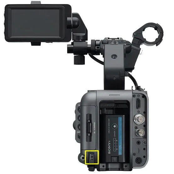
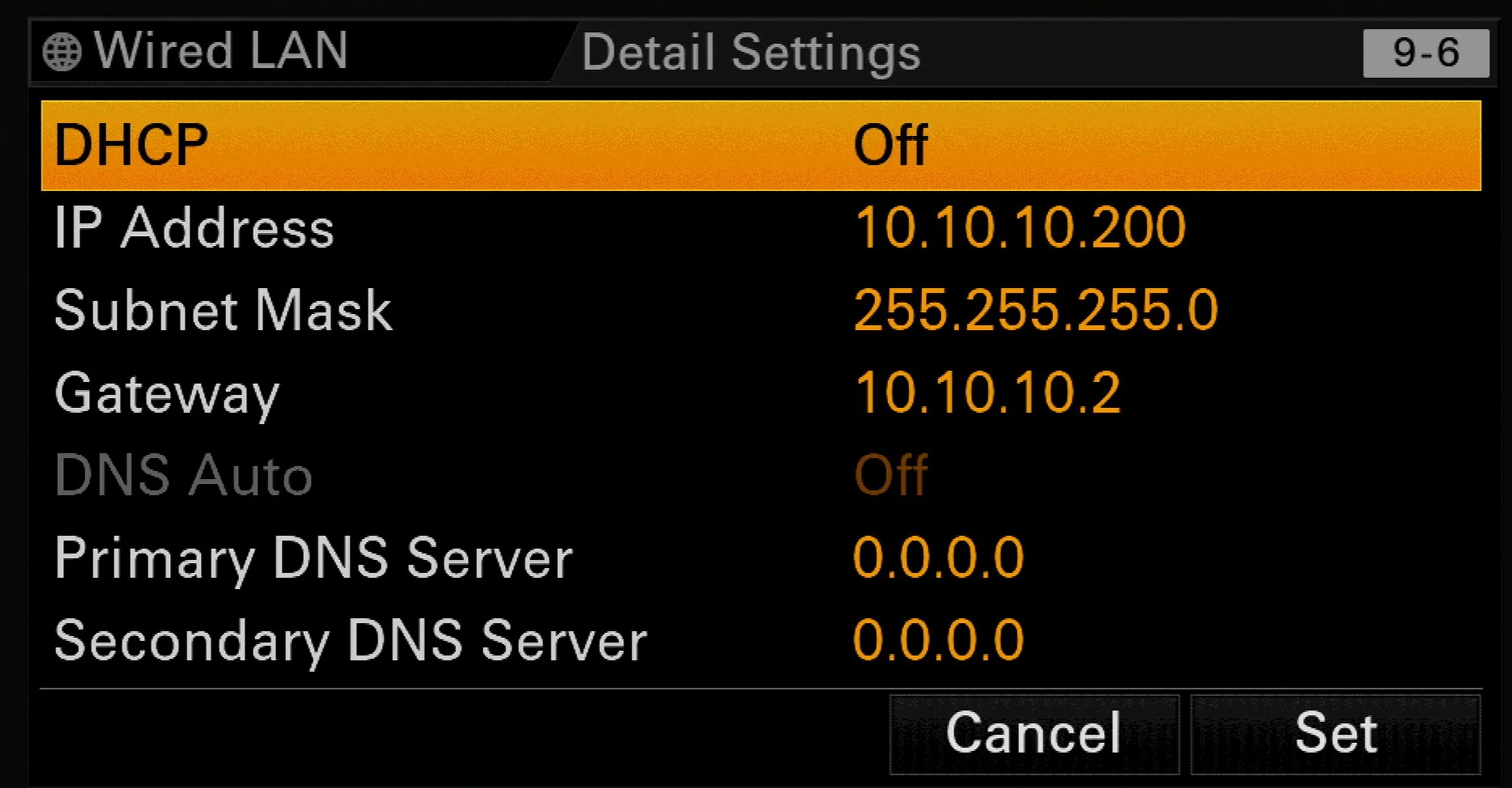
The only USB-C to Ethernet adapter we recommend and have verified to work with the Sony FX6 and Core Link is the SmallHD USB-C to Ethernet Adapter. While other adapters may function, we do not recommend using them with Core Link.
Sony FX3
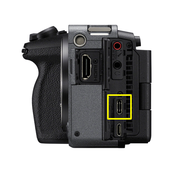
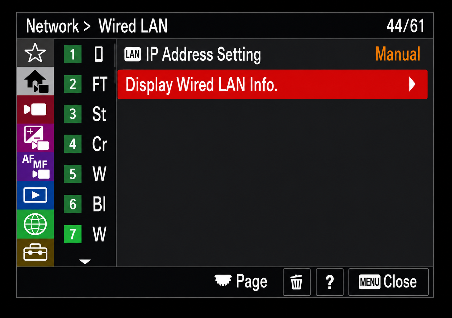
Connect Core Link to the FX3 using Ethernet and a compatible USB-C to Ethernet adapter. Connect the Ethernet cable from the Core Link network to the adapter, then plug the adapter into the FX3 USB Type-C terminal.
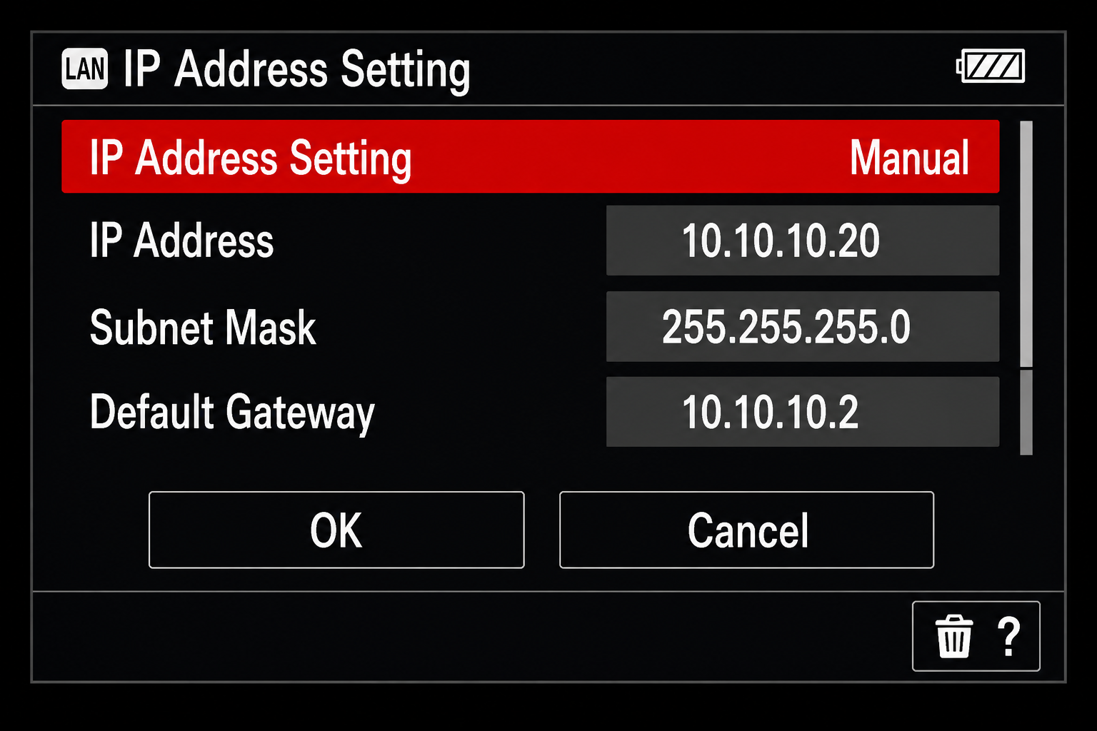
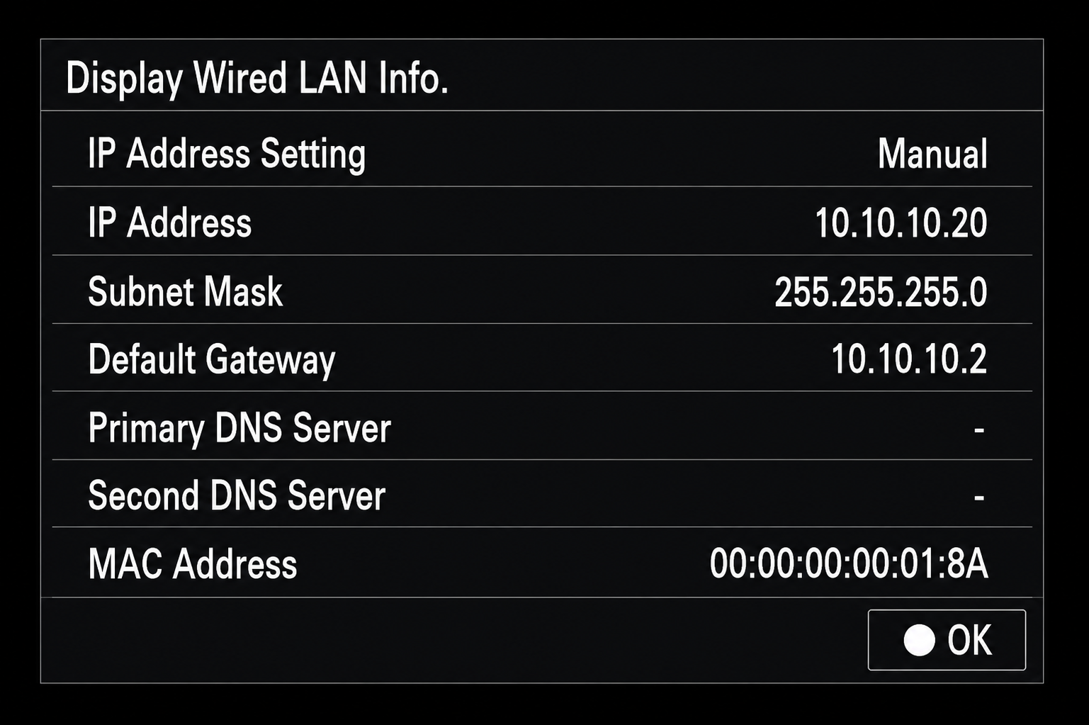
On the FX3, go to Network → Wired LAN → Wired LAN and set it to On. Then open Wired LAN IP Settings, change IP Address Setting to Manual, and enter the network values shown above. Select OK to save the configuration.
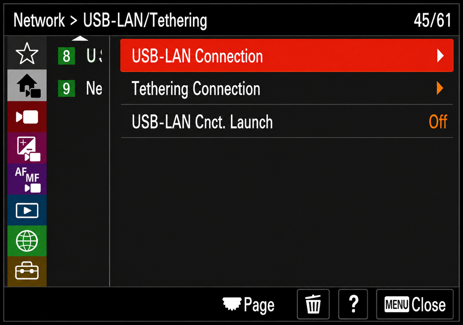
Return to the main Network menu, navigate to USB-LAN/Tethering → USB-LAN Connection, and select it. The camera will display “Preparing Connection...” and start the wired network connection using the saved manual IP profile.
The only USB-C to Ethernet adapter we recommend and have verified to work with the Sony FX6 and Core Link is the SmallHD USB-C to Ethernet Adapter. While other adapters may function, we do not recommend using them with Core Link.
Blackmagic PYXIS 6K / 12K
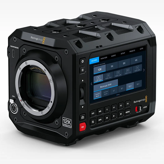
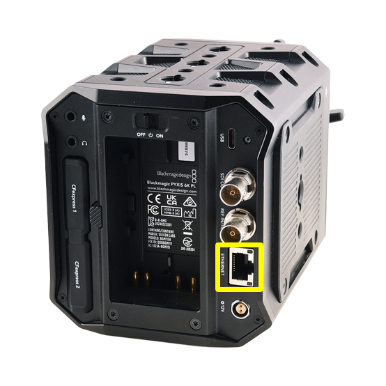
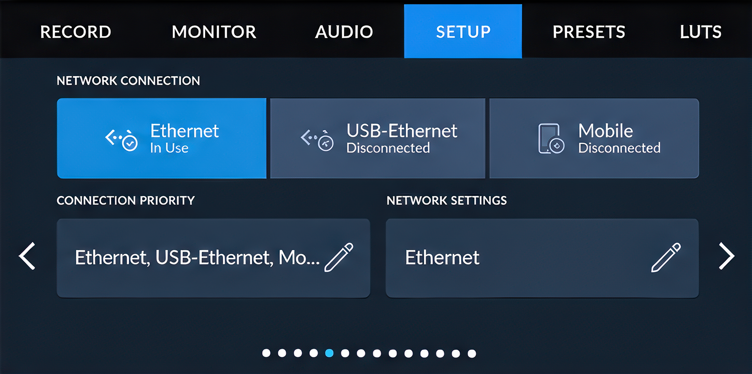
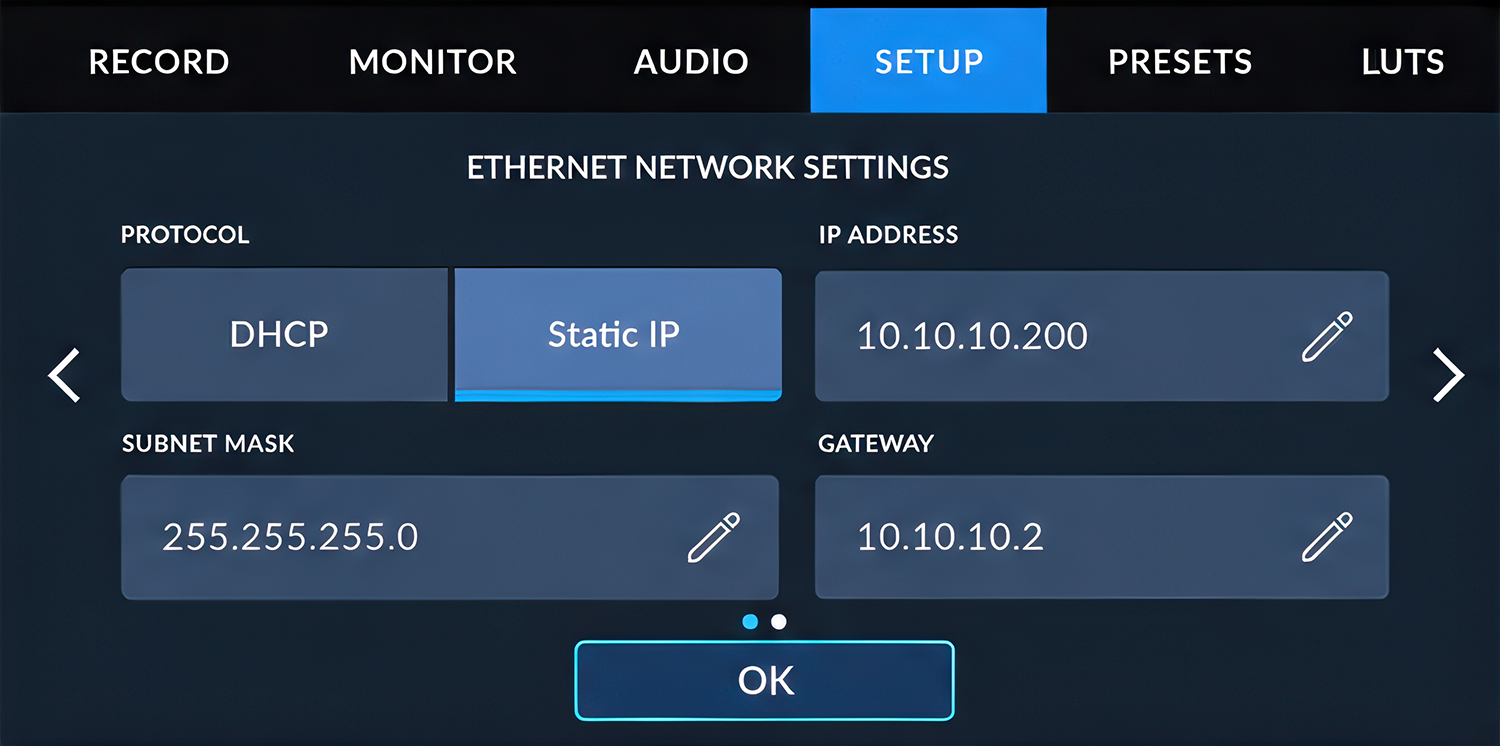
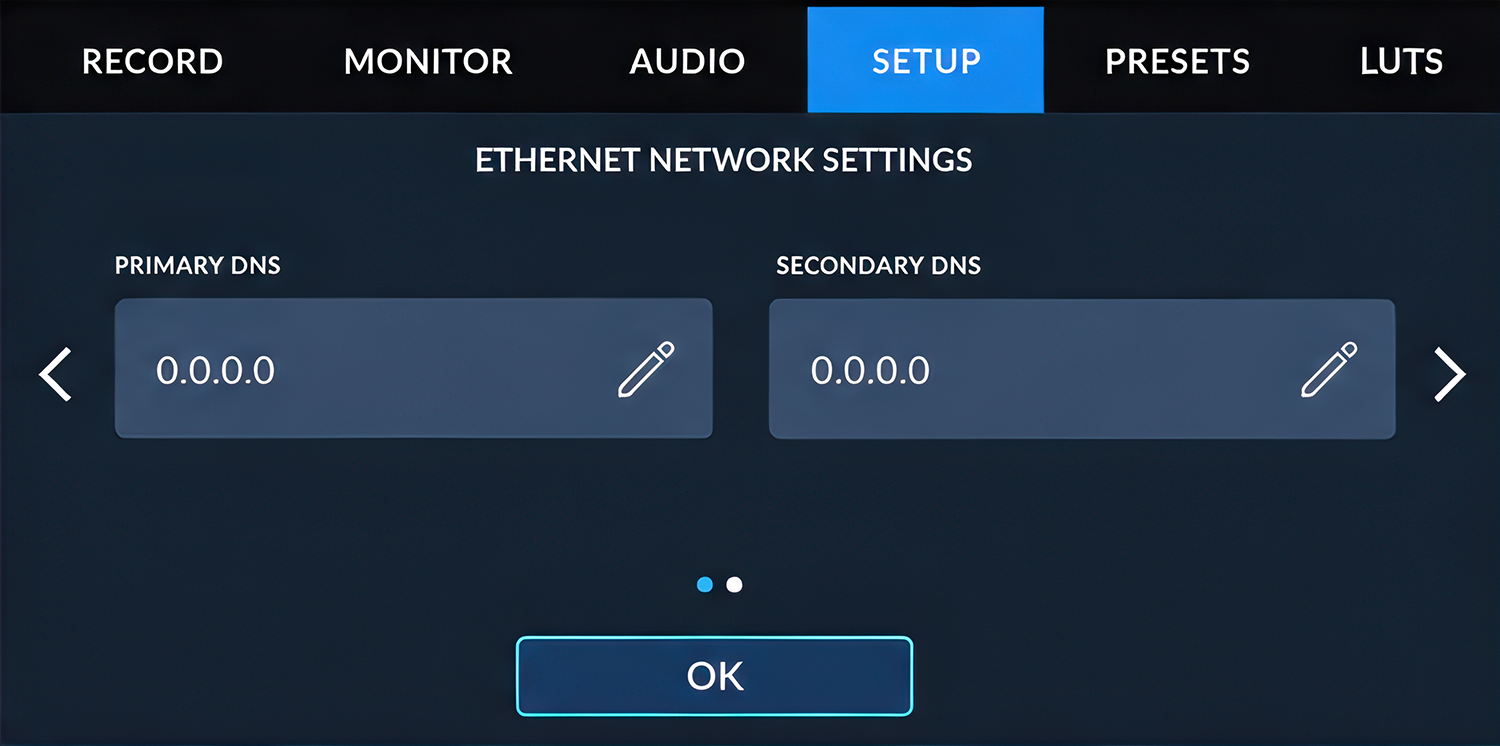
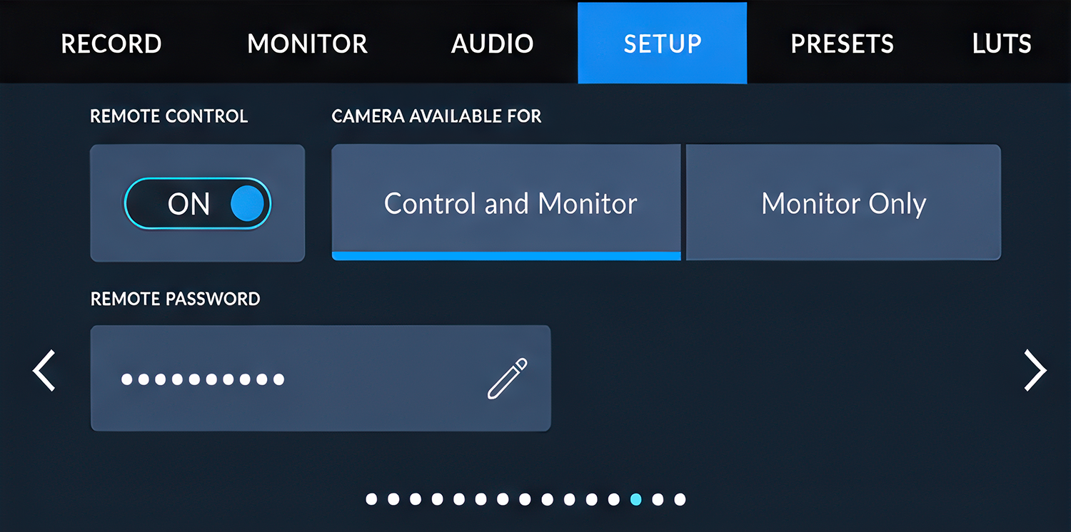
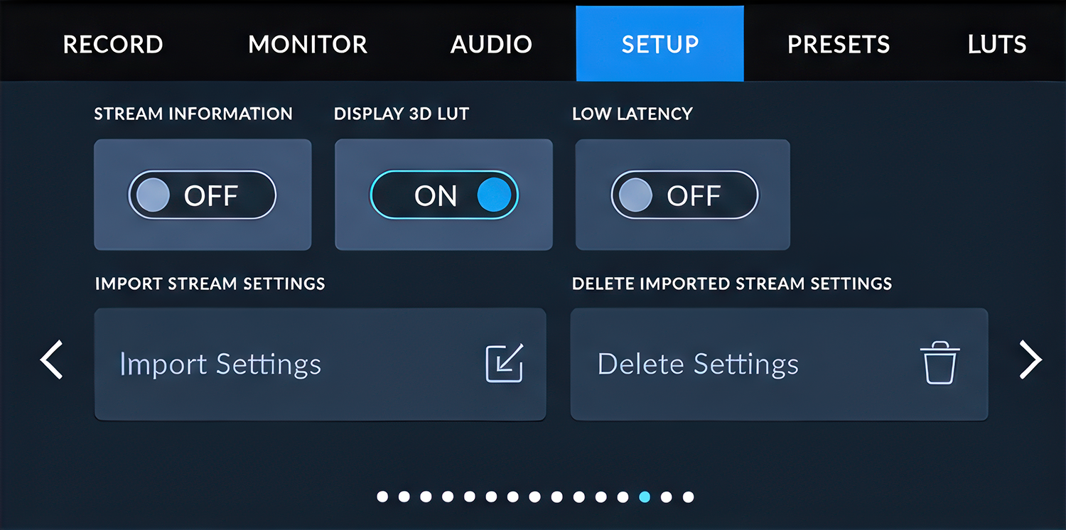
Use the same case-sensitive password when connecting Core Link or another remote-control device to the camera.
Set Stream Information to Off to reduce unnecessary status information on the camera monitor.
iPhone & iPad Setup
Configure the Ethernet connection manually before opening your preferred camera-control application.
Configure the Control Device
- Turn Wi-Fi off on the iPhone or iPad.
- Connect the Ethernet adapter.
- Open Settings → Ethernet.
- Select Configure IP → Manual.
- Enter the settings shown below.
Open Safari, ARRI Companion, Sony Monitor & Control, Blackmagic Camera app, or your preferred control application and enter the camera’s IP address.
Connection Support
No Connection
- Verify power to both Core Link units.
- Verify both Ethernet connections.
- Confirm the camera and control device are on the same subnet.
Unable to Pair
- Confirm one unit is configured as RX.
- Confirm the other unit is configured as TX.
- Repeat the pairing procedure.
Reduced Range
- Move the RX to a more central location.
- Verify the antennas are installed correctly.
- Reduce the number of active TX units when maximum range is required.